A Tutorial On Pipe Flow Equations
Particular emphasis is placed on those used within the natural gas industry in hopes that engineers within that industry can make knowledgeable decisions on how to model pipes. Consider such a case for horizontal flow in which PE.
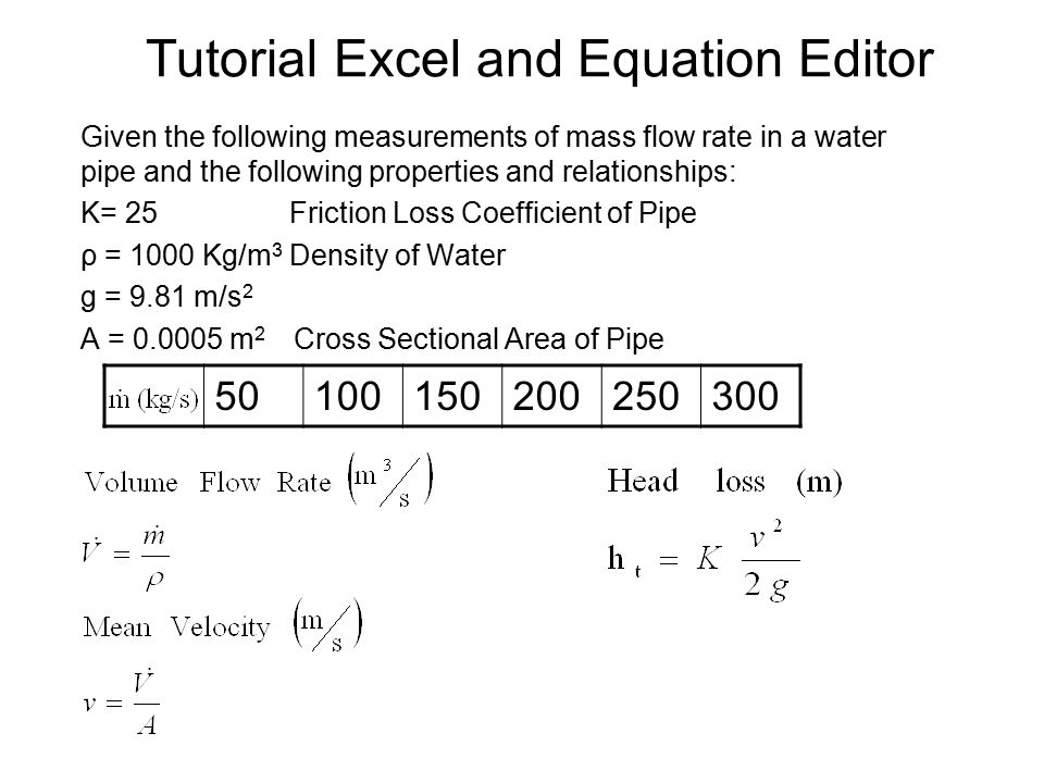
Tutorial Excel And Equation Editor Given The Following Measurements Of Mass Flow Rate In A Water Pipe And The Following Properties And Relationships K Ppt Download
Add at least 15 times the velocity head to get the headwater depth or see my 2-minute tutorial for standard culvert headwater calculations using HY-8.
A tutorial on pipe flow equations. Draw and solve a classic three reservoirs flow problem using Pipe Flow Expert. The purpose of this paper is to describe the equations which govern the flow of compressible fluids through pipes. This tutorial shows how to run a CFD analysis of the flow inside a pipe with multiple inlets using our free CFD software SimWorks.
Showing the parameters in the equations. Figure 9 u2 0 and z1 z2 so CpT1 u122 C pT2 0 T2 u122Cp T1 T2 is the stagnation temperature for this case. This tutorial model illustrates how to calculate the pressure drop and initial flow rate in a pipe system connected to water tank.
This is the flow and depth inside the pipe. About Press Copyright Contact us Creators Advertise Developers Terms Privacy Policy Safety How YouTube works Test. 00010 - Revisiting velocity profile of fully-developed laminar flows Poiseuilles law00307 - Head loss of fully-developed laminar flows in straight pip.
Q - Pipe Flow Rate. Set the Convergence Criterion to be 1e-06 for all five equations being solved. Volumetric flow rate.
SolidWorks add-ins enable you to simulate flow of liquids and gases and efficiently analyse the effects of fluid flow. The purpose of this paper is to describe the equations which govern the flow of compressible fluids through pipes. The author is extremely indebted to the following two groups of engineers for developing its concepts fully.
Fully developed incompressible Newtonian flow through a straight circular pipe. A Tutorial on Pipe Flow Equations by Donald W. Calculation of the area of flow and the wetted perimeter are slightly different than those calculations for the less than half full case.
Fluid flow may be very hard to predict and differential equations that are used in fluid mechan-ics are difficult to solve. Where S - hydraulic gradient v - kinematic viscosity of water D - Internal diameter Ks - Roughness coefficient g Gravity 981 ms 2 A - Area of section. This will print as well plot the residuals as they are calculated which you will use to monitor convergence.
The results will show the local pressure distribution inside the pipe. ANSYS Tutorial Fluid Flow Analysis in a U-Bend Pipe using ANSYS Fluent ANSYS CFD Tutorials. 44 Re DV DV Q m DD ρ µ ν πν π µ where.
The Pipe Flow interface contains ready to use friction models accounting for the surface roughness of pipes as well as pressure losses in bends and valves. 00128m ³ s 1012m 2. The atmospheric pressure head is 1035m.
The purpose of this study is to simulate flow in pipes utilizing SolidWorks software. Notice that Convergence Criterion has to be set for the k and epsilon equations in addition to the three equations in the last tutorial. ρ is the density of the fluid µ is its dynamic viscosity and ν µρ is the kinematic viscosity.
Getting the flow into the pipe may require significantly higher headwater depth. Assume f 0006 and take the entrance loss as 05 u²2g and the exit loss as 1u²2g. Box 86 Carlisle Pennsylvania 17013-0086 August 16 2001 Preface and Dedication This paper is a form of plagiarism for it contains few new thoughts.
For more than half full pipe flow the parameter h is 2r y instead of simply being equal to y as for less than half full pipe flow. The tutorial will guide you in the setup of the simulation of a pipe with different inlets. Particular emphasis is placed on those used within the natural gas industry in hopes that engineers within that industry can make knowledgeable decisions on how to model pipes.
Edges of any obstacle placed in the flow and in instruments such as a Pitot Tube. ANSYS Tutorial Fluid Flow Analysis in a U-Bend Pipe using ANSYS Fluent ANSYS CFD. If the water level in the reservoir at A is 37m above the pipe and at C the level is 1m above the pipe calculate the quantity which will flow and the pressure head in the pipe at B.
The area of flow is calculated as. 2 4 Q DV π where D is the pipe diameter and V is the average velocity. Please give us your valued words of suggestion or praise.
Select Print to Console and Plot under Options these are the defaults.
Pipe Flow Problem Determine Diameter Youtube

The Manning Equation For Partially Full Pipe Flow Calculations Pages 1 26 Flip Pdf Download Fliphtml5

Simulating Flow Through A Pipe Using Openfoam Skill Lync
Pipe Water Velocity And Minimum Pipe Diameter Calculator